
Views: 0 Author: Site Editor Publish Time: 2026-09-28 Origin: Site
Procuring capital manufacturing equipment carries high operational stakes. A misaligned machine configuration directly impacts production bottlenecks, excessive tool wear, and compromised part quality. Investing in a CNC lathe machine requires precise alignment between specific production requirements—such as part geometry, batch volume, and material hardness—and the mechanical capabilities of the turning center. Overspending on unnecessary multi-axis capabilities traps capital. Under-speccing machine rigidity leads to chatter, poor surface finishes, and an inability to hold tight tolerances during hard turning.
This technical evaluation framework provides production managers, machinists, and procurement teams with the criteria to navigate machine specifications, structural categories, and implementation realities. By understanding the mechanical nuances of spindle torque, guideway construction, and tooling interfaces, manufacturing facilities can deploy turning solutions that maximize throughput and maintain stringent quality standards.
Configuration Dictates Capability: Horizontal lathes optimize for high-speed, continuous bar-fed production, while vertical lathes are mandatory for heavy, large-diameter, or awkwardly shaped workpieces.
Axis Complexity vs. ROI: Upgrading from a standard 2-axis lathe to a multi-axis machine with live tooling reduces setup times and handling errors but requires a rigorous ROI analysis based on part complexity and volume.
Rigidity is Non-Negotiable: Machine weight, casting design (e.g., slant bed), and guideway types (box vs. linear) directly impact tool life, surface finish, and the ability to hold tight tolerances during hard turning.
Implementation Extends Beyond the Machine: Initial purchase price rarely accounts for necessary workholding, tooling packages, chip management systems, and CAM software integration.
Table of Contents
The fundamental operation of a turning center relies on rotating a workpiece at high speeds on a spindle while a cutting tool, mounted to a rigid turret, moves linearly across multiple axes to remove material. This kinematic relationship shapes raw stock into precise cylindrical, conical, or symmetrical components. Unlike manual turning, a modern CNC Lathe Machine utilizes closed-loop servomotors and precise feedback systems to execute complex toolpaths with sub-micron accuracy. The integration of digital controls allows shops to transition from rough stock to a finished component in a single setup.
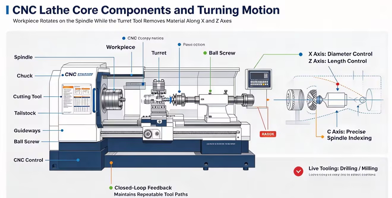
A CNC lathe has several main parts that work together to machine a workpiece. The spindle rotates the material and determines the machine's speed, torque, and bar capacity, while the chuck or collet holds the material securely. The turret holds the cutting tools and moves them between operations, and its rigidity affects cutting performance and vibration. The tailstock supports long parts and helps prevent bending during machining. The CNC control unit controls the machine's movements and functions such as coolant and chip removal.
A standard two-axis CNC lathe can perform several common machining operations, including turning, facing, threading, and grooving. Turning reduces the outside diameter, facing creates a flat end surface, threading creates internal or external threads, and grooving cuts narrow grooves into the part. CNC lathes can also produce tapered and curved surfaces with programmed toolpaths.
The main difference between turning and milling is which part rotates. In turning, the workpiece rotates while the cutting tool removes material. In milling, the workpiece usually stays in place while the cutting tool rotates. Some CNC lathes can perform both operations when equipped with live tooling, a C-axis, and a Y-axis, allowing them to machine features such as holes, flats, and keyways without moving the part to another machine.
Upgrading from a conventional lathe to a CNC lathe can improve production speed, accuracy, and consistency. The right time to upgrade depends mainly on production volume, part complexity, accuracy requirements, and labor needs.
Conventional lathes are useful for one-off parts, repairs, prototypes, and very small production runs. CNC lathes become more useful when the same part needs to be produced repeatedly because they can automate tool movements, tool changes, and cutting speeds. For larger batches, CNC machines can reduce cycle times and produce more consistent parts with less operator intervention.
Conventional lathes depend heavily on the operator's skills and manual adjustments, which can cause small differences between parts. CNC lathes use feedback systems to check axis positions and make precise movements, allowing them to produce many parts with consistent dimensions. Some CNC controls also compensate for changes caused by machine temperature, helping maintain accuracy during long production runs.
Conventional lathes use handwheels and leadscrews, while CNC lathes use motors and precision ballscrews to control axis movement. CNC machines can move multiple axes automatically and provide more consistent positioning. They also normally have enclosed machine areas that contain coolant and metal chips, making the machining process cleaner and safer.
CNC lathes reduce the amount of manual work required from operators. Instead of controlling the machine by hand throughout the entire process, operators can load material, set tools, monitor tool wear, and manage multiple machines. CNC production also requires skills in machine setup, programming, and CAM software, allowing experienced machinists to spend more time on programming and process improvement.
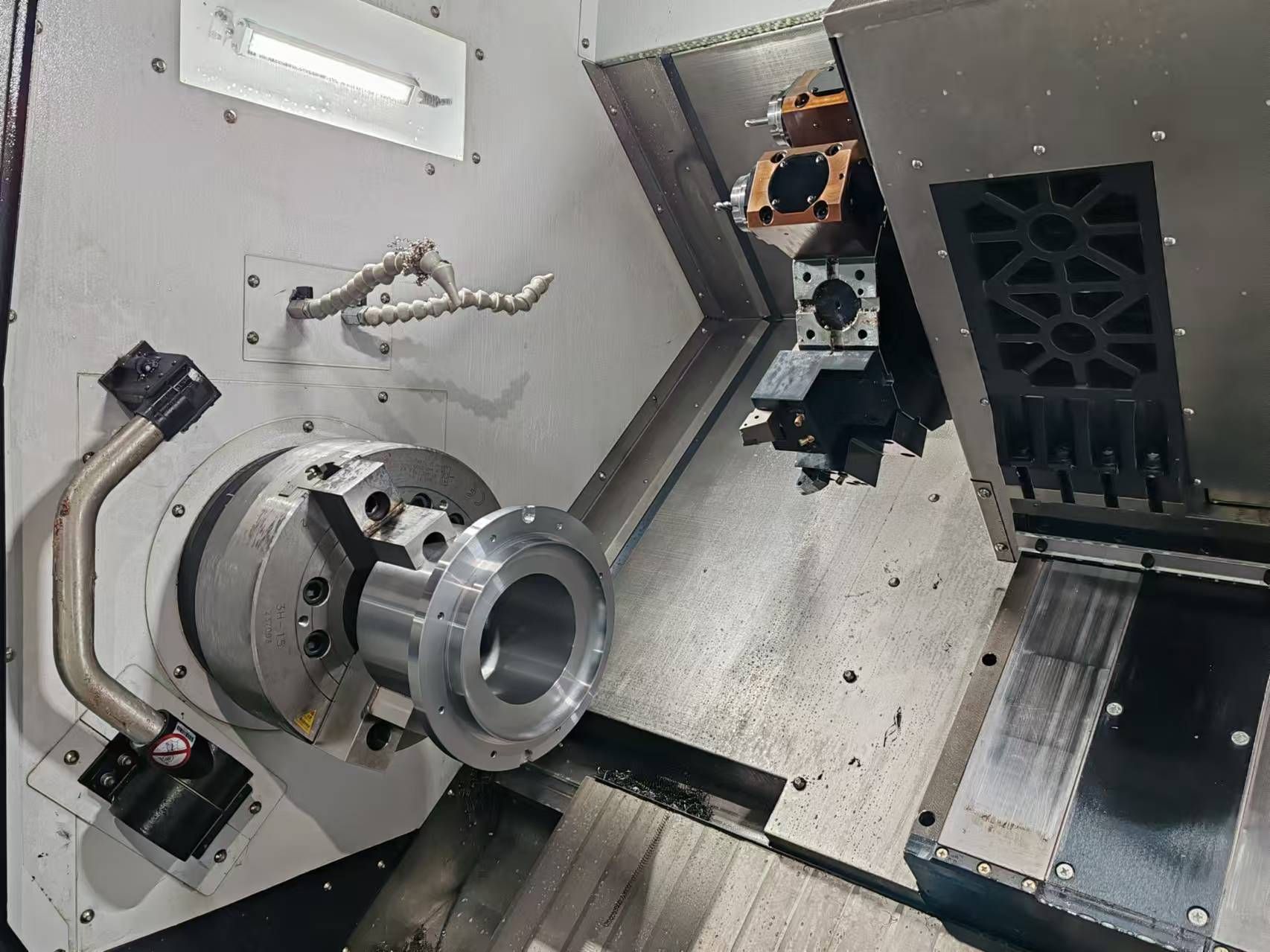
Selecting the correct machine architecture is the most consequential decision in the procurement process. Turning centers are categorized by their spindle orientation and axis configurations, each engineered for specific part geometries and production environments.
Horizontal CNC lathes are the most common type used in machine shops. Their spindle is positioned horizontally, making them suitable for producing shafts, pins, bushings, and other bar-stock parts. Many models use a slant bed that improves machine stability and helps move chips and coolant away from the cutting area. Horizontal lathes also work well with automation, such as bar feeders and automatic part catchers, making them a good choice for high-volume production.
Vertical CNC lathes have a spindle that points upward, with the chuck positioned horizontally. This design makes it easier to load and hold large, heavy parts because the workpiece can rest on the chuck. VTLs are commonly used for large-diameter and heavy parts, such as brake rotors, turbine rings, pump housings, and large flanges. They also take up less floor space than a horizontal lathe with a similar turning capacity.
Multi-axis CNC lathes can perform more operations in one setup than standard two-axis machines. Additional axes, live tooling, and a sub-spindle allow the machine to drill, mill, and machine both sides of a part without moving it to another machine. Swiss-type CNC lathes are designed for small, long, and thin parts. They use a sliding headstock and guide bushing to support the material close to the cutting tool, which helps reduce bending and vibration. They are commonly used for small precision parts such as medical screws and other miniature components.
The structural rigidity, spindle torque, and tooling configurations of a turning center dictate its suitability for specific industrial sectors. Different manufacturing fields demand specialized machine characteristics to handle unique alloys and tolerance requirements.
Aerospace manufacturing involves machining high-temperature superalloys like Inconel, Hastelloy, and aerospace-grade Titanium. These materials exhibit extreme toughness and rapid work-hardening characteristics. Machining them requires turning centers with exceptional rigidity, heavy cast-iron bases, and high-torque geared spindles. Any vibration during the cut will instantly chip carbide inserts and ruin the workpiece. Thermal stability is equally critical; aerospace components often require tolerances tighter than 0.0005 inches, meaning the machine must compensate for thermal expansion during long cutting cycles.
The automotive sector prioritizes cycle time optimization and high-volume throughput. Turning centers in this industry are typically configured for rapid material removal on carbon steels, cast iron, and aluminum alloys. Applications include machining transmission shafts, engine valves, CV joints, and custom fasteners. Automotive turning cells rely heavily on robotic gantry loaders, twin-spindle configurations, and high-speed linear guideways to shave seconds off every cycle, maximizing daily output.
Medical manufacturing demands pristine surface finishes and the machining of biocompatible materials such as 316L stainless steel, titanium alloys, and engineered plastics like PEEK. Swiss-type turning centers dominate this sector. The production of dental implants, spinal hooks, bone screws, and surgical instruments requires micro-machining capabilities, high-pressure coolant to evacuate stringy titanium chips, and extreme precision to ensure parts mate perfectly in surgical applications.
The oil and gas industry requires heavy-duty turning centers capable of handling massive workpieces. Machining drill pipes, wellhead flanges, and downhole tools requires machines with exceptionally long bed lengths, large spindle through-holes to accommodate heavy pipe stock, and programmable steady rests to support the middle of long parts. These machines must generate immense low-end torque to push large threading inserts through tough alloy steels, cutting deep API threads without stalling the spindle.
Evaluating a turning center requires looking past marketing specifications and analyzing the mechanical engineering of the machine. The following technical dimensions dictate how a machine will perform on the shop floor.
The size of a CNC lathe determines the maximum workpiece it can safely machine. Swing over bed refers to the largest diameter that can rotate without hitting the machine bed, while swing over cross slide shows the largest diameter that can be turned while giving the cutting tool enough clearance. The maximum turning length depends on the machine's Z-axis travel. For parts longer than three times their diameter, a tailstock is usually needed to prevent the workpiece from bending away from the cutting tool. For very long shafts, a programmable steady rest can support the middle of the workpiece, reduce vibration, and help maintain accuracy.
The spindle's speed, power, and torque should match the materials and parts you plan to machine. High spindle speeds, such as 5,000 to 10,000 RPM, are useful for small-diameter parts and materials such as aluminum and brass because they help achieve good chip removal and surface finish. Large-diameter steel parts and hard alloys require more torque at lower speeds. Direct-drive spindles provide fast acceleration, high speeds, and low vibration, making them suitable for finishing work. For heavy cutting and hard turning, belt-driven or gear-driven spindles provide higher low-speed torque and help prevent the spindle from slowing down or stopping during deep cuts.
The foundation of any turning center is its casting. High-quality machines utilize Meehanite cast iron or advanced polymer concrete bases, which possess superior vibration-damping properties compared to standard welded steel. The type of guideways mounted to this casting determines the machine's dynamic behavior.
Guideway Type | Mechanical Design | Primary Advantages | Best Use Cases |
|---|---|---|---|
Box Ways | Solid cast iron tracks, precision ground and hand-scraped. Metal-on-metal sliding contact with oil film. | Maximum rigidity, exceptional vibration damping, high load capacity, superior shock absorption. | Heavy roughing, interrupted cuts, hard turning, aerospace alloys (Inconel, Titanium), large forgings. |
Linear Guide Ways | Rails utilizing recirculating ball or roller bearings. Rolling contact rather than sliding friction. | High rapid traverse rates, zero stick-slip friction, fast acceleration, lower thermal generation. | High-volume production, light to medium cutting, aluminum, brass, fast cycle times, small parts. |
The turret determines how many tools a CNC lathe can hold at one time. A 12-station turret is enough for most basic work, while machines used for complex or high-volume parts may need 16 or 24 stations to hold more tools and reduce tool changes. However, larger turrets can increase the risk of tool interference. For machines with live tooling, the turret interface also affects machining performance. VDI holders allow fast tool changes, while BMT holders provide better rigidity and are better suited for heavy milling and drilling.
Procuring a turning center involves logistical and operational complexities that extend far beyond the delivery of the machine. Failing to account for these implementation requirements leads to delayed production launches and unexpected operational friction.
The base machine rarely includes the peripheral systems necessary for efficient production. You must account for several critical additions:
High-Pressure Coolant Systems: Often requiring 300 to 1,000 PSI, these are mandatory for deep hole drilling and breaking chips in stringy materials like low-carbon steel.
Chip Management: Hinge belt conveyors work well for stringy steel chips, while magnetic conveyors are required for cast iron fines.
Mist Collectors: High-speed turning generates coolant mist that must be extracted to maintain shop air quality and protect electronics.
Specialized Workholding: Custom bored soft jaws, collet chucks, and sub-spindle ejectors must be engineered and procured prior to machine arrival.
Industrial turning centers are exceptionally heavy and require specific foundation preparations. Placing a rigid box-way machine on thin, unreinforced concrete will cause the machine bed to twist as the concrete flexes, making it impossible to hold tight tolerances. Core drilling and pouring isolated concrete pads may be necessary. Electrical supply stability is critical; CNC controls are highly sensitive to voltage fluctuations. Facilities running on uneven power grids must install rotary phase converters or dedicated isolation transformers. Climate control also plays a role; temperature swings in the shop environment cause thermal expansion in the machine casting, leading to dimensional drift throughout the day.
Integrating a new machine control architecture introduces a learning curve for operators and programmers. Existing CAM software must be updated with accurate post-processors specifically written for the new machine's kinematic layout. A poorly configured post-processor will generate G-code that causes axis over-travels or catastrophic spindle crashes. Allocating time for comprehensive operator training on the specific control interface, tool presetting routines, and daily maintenance schedules is essential for a smooth operational ramp-up.
Deploying the optimal turning center requires balancing part geometry, production volume, and mechanical capabilities. A machine configured with excessive multi-axis complexity will inflate capital expenditures and complicate programming, while a machine lacking sufficient structural rigidity will struggle to maintain tolerances and consume cutting tools at an unsustainable rate.
When shortlisting equipment, prioritize machine mass, box-way construction, and high-torque gearboxes for machining tough aerospace and oil-field alloys. Prioritize linear guideways, high spindle RPM, and automated bar-feeding integration for high-volume aluminum or brass component production.
To finalize the selection process, execute the following actionable steps:
Request a detailed time study from the machine tool builder based on your specific part prints to verify cycle time estimates.
Demand a physical test cut on the proposed machine using your actual raw material to validate surface finish and tolerance capabilities.
Audit the shop floor for foundation depth, electrical capacity, and compressed air volume before scheduling machine rigging and delivery.
Verify that your current CAM software provider has a proven, bug-free post-processor available for the exact machine and control combination being purchased.
A: A normal lathe relies on manual handwheels and acme leadscrews, requiring constant operator intervention and skill to maintain tolerances. A CNC lathe replaces manual controls with computer numerical control, closed-loop servomotors, and precision ballscrews. This digital architecture automates toolpaths, provides sub-micron repeatability, and executes complex geometries at high speeds without human error.
A: Yes, when configured as a mill-turn center. By adding a C-axis for precise spindle indexing and live tooling on the turret, the machine can drill, tap, and mill on the part's centerline. Integrating a Y-axis provides vertical turret movement, enabling off-center milling, flat machining, and complex pocketing directly on the lathe without transferring the part to a separate milling machine.
A: An industrial turning center typically operates reliably for 10 to 15 years in a standard production environment. Lifespan depends heavily on cutting parameters, material hardness, and adherence to preventative maintenance schedules. Machines running heavy interrupted cuts on tough alloys will experience faster mechanical wear than those turning aluminum. Regular lubrication, geometry checks, and avoiding physical crashes significantly extend operational life.
A: Turning centers process a massive variety of materials, including aluminum, brass, carbon steel, stainless steel, cast iron, titanium, and engineered plastics like PEEK. Machining harder alloys requires specific machine configurations. Tough materials demand high-torque gear-driven spindles and rigid box-way construction to prevent vibration and premature tool failure, while softer materials benefit from high-RPM direct-drive spindles and fast linear guideways.
A: A Swiss lathe features a sliding headstock that feeds raw bar stock through a stationary guide bushing. The cutting tools remain fixed right at the bushing face, supporting the material exactly where the cut occurs. This design eliminates bar deflection. It is absolutely required for machining long, slender parts with a length-to-diameter ratio greater than 3:1, such as medical bone screws.


