
Views: 0 Author: Site Editor Publish Time: 2026-09-28 Origin: Site
While basic milling changed manufacturing, the modern CNC machining center consolidates milling, drilling, tapping, and boring into a single automated cell. Misunderstanding the underlying mechanics, drive systems, and axis configurations leads to misaligned equipment investments. It also causes engineers to select outsourcing partners incapable of meeting strict tolerance and cycle-time requirements. Deconstructing exactly how a CNC Machining Center works provides the technical foundation necessary to evaluate machine capabilities. You need this knowledge to assess vendor competencies and align equipment specifications with actual production outcomes. We will break down the kinematics, thermal management, and multi-axis configurations that dictate part quality. By understanding the physical differences between linear guideways and box ways, or positional versus simultaneous multi-axis movement, you can optimize your shop floor for maximum throughput and precision.
Automation Distinguishes the Center: The integration of an Automatic Tool Changer (ATC) and automatic pallet changers shifts a standard mill into a high-throughput machining center.
Configuration Dictates Efficiency: The mechanical differences between Vertical (VMC) and Horizontal (HMC) centers directly impact chip evacuation, fixturing strategies, and cost-per-part at scale.
Axis Capabilities Define Part Complexity: Understanding the mechanical leap from 3-axis to simultaneous 5-axis machining is critical for evaluating setup reduction and geometric limitations.
Thermal and Dynamic Stability Drive Precision: A machine’s ability to hold tight tolerances depends heavily on its casting rigidity, linear guideways, and thermal compensation systems.
Digital Integration is Non-Negotiable: Modern centers rely on advanced CAM software, digital twins, and IoT monitoring to maximize spindle uptime and prevent catastrophic crashes.
Table of Contents
The Machine Control Unit (MCU) is the main control system of a CNC machine. It converts G-code into electrical signals that control the servo motors, spindle speed, feed rate, and axis movement. Advanced controls use look-ahead functions to read many program blocks in advance, helping the machine maintain smooth movement during high-speed machining and complex 3D cutting. A 1000-block look-ahead can reduce sudden slowdowns, surface marks, and longer cycle times.
Servo motors drive the ball screws to convert rotary motion into precise linear axis movement. Closed-loop feedback systems use encoders and linear scales to compare the actual position with the programmed position and correct errors caused by backlash or heat. Box ways provide high rigidity and vibration control for heavy cutting and hard materials, while linear guideways have lower friction and support fast movement and high-speed machining, making them suitable for aluminum and high-volume production.
The spindle holds and rotates the cutting tool and is available with common tapers such as CAT40, BT40, and HSK63. Direct-drive spindles provide high speed for fine finishing, gear-driven spindles provide high torque for heavy cutting, and belt-driven spindles offer a balance of speed and torque. The Automatic Tool Changer (ATC) stores and changes tools automatically, reducing non-cutting time. Faster chip-to-chip tool changes can significantly reduce cycle time in high-volume production.
Workholding systems keep the part securely and accurately positioned during machining. Zero-point fixtures allow quick and repeatable fixture changes, while hydraulic and pneumatic clamps provide consistent clamping force and help prevent part movement or distortion. Automatic Pallet Changers (APCs) use two or more pallets so operators can load and inspect parts outside the machine while another pallet is being machined, reducing setup time and increasing spindle utilization.
VMCs have a vertical spindle that moves along the Z-axis above the workpiece. They provide good visibility, simple setup, and easy integration with 4th-axis rotary tables, making them suitable for job shops and a wide range of parts. VMCs work well for single-sided parts, large plates, die and mold machining, and heavy roughing where strong workholding is needed.
HMCs have a horizontal spindle that allows chips to fall away from the cutting area, reducing chip recutting and improving tool life. This makes them suitable for deep pockets and complex internal features. HMCs commonly use tombstone fixtures that can hold multiple parts on several sides, while the B-axis rotates the fixture to present each side to the spindle, allowing more parts to be machined in one cycle and supporting longer unattended production.
Mill-turn machines combine turning and milling in one machine, using features such as a main spindle, sub-spindle, live tooling, ATC, and Y-axis movement. They can machine complex cylindrical parts with off-center holes, milled features, and other details in one setup. This reduces part transfers, setup time, and positioning errors, while improving accuracy for complex parts used in industries such as aerospace and medical manufacturing.
Feature | Vertical Machining Center (VMC) | Horizontal Machining Center (HMC) |
|---|---|---|
Spindle Orientation | Vertical (Perpendicular to table) | Horizontal (Parallel to floor) |
Chip Evacuation | Poor to Moderate (Gravity works against it) | Excellent (Chips fall away from part) |
Fixturing Strategy | Flat vises, single-plane clamping | Tombstones, multi-face processing |
Floor Space | Compact footprint | Large footprint (requires APC space) |
Ideal Production Volume | Low to Medium (High mix) | Medium to High (Unattended running) |
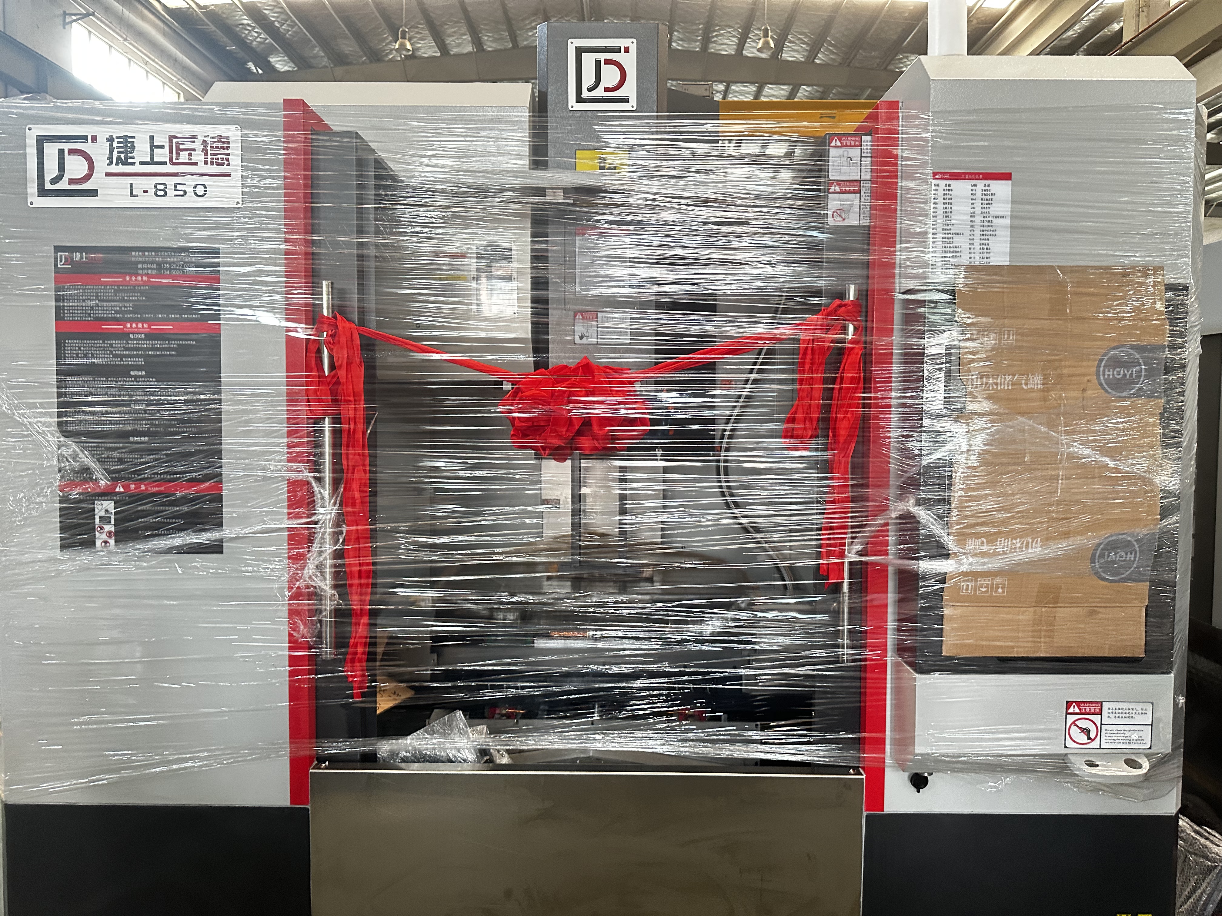
A 3-axis machine moves the cutting tool along the X, Y, and Z axes. It can machine many 2.5D and 3D shapes, but the tool remains in a fixed vertical direction, which limits access to undercuts, side holes, and angled surfaces. Parts with features on multiple sides often need several setups, requiring the operator to unclamp, reposition, and re-clamp the part, which adds setup time and can reduce positioning accuracy.

4-axis and 5-axis machines add rotary axes, allowing the tool to reach the part from different angles. In 3+2 machining, the rotary axes move the part to a set angle and then lock while the machine performs standard 3-axis cutting. In simultaneous 5-axis machining, all five axes move together while the CNC control continuously adjusts the tool direction. This is useful for complex parts such as impellers, turbine blades, and aerospace components because it provides better tool access and surface finish.
Investing in 5-axis mechanics requires justifying the mechanical overhead. Decision-makers must align machine capabilities with specific geometric outcomes. A 5-axis setup is justified when parts feature deep cavities that require short, rigid cutting tools to prevent deflection. Tilting the tool away from the cavity wall allows for aggressive feed rates without chatter. Additionally, if a component requires tight true-position tolerances across multiple angled faces, eliminating manual setups via 5-axis positioning is the only reliable manufacturing method.
Axis Configuration | Kinematic Movement | Primary Advantage | Typical Application |
|---|---|---|---|
3-Axis | X, Y, Z linear only | High rigidity, simple programming | Flat plates, simple brackets, 2.5D profiles |
3+2 Axis (Positional) | X, Y, Z linear + locked A/B/C rotary | Reduces manual setups, accesses multiple sides | Multi-sided valve bodies, complex housings |
5-Axis (Simultaneous) | X, Y, Z, A, B/C moving together | Continuous tool engagement, superior surface finish | Aerospace impellers, turbine blades, medical implants |
Tool presetting systems measure tool length and diameter before or during machining, while in-machine probes can check tool wear and breakage. When a tool reaches its wear limit, the CNC control can update the tool offset or switch to a sister tool automatically. Spindle probes can also set work offsets, align the part, and measure key dimensions during machining, helping reduce setup time, scrap, and manual inspection.
Through-Spindle Coolant (TSC) sends high-pressure coolant through the spindle and cutting tool to remove heat and chips directly from the cutting area. Typical pressure ranges from 300 to 1,000 PSI. TSC is especially useful for deep-hole drilling and machining materials such as titanium and 304 stainless steel, where heat and chip buildup can quickly damage tools and reduce tool life.
Efficient chip removal prevents chip buildup, machine jams, and poor coolant flow. Chip augers, belt conveyors, and washdown systems move chips out of the machining area, while coolant filters and cyclonic separators remove fine particles from the coolant. Oil skimmers remove unwanted oil from the coolant tank, helping maintain coolant quality, surface finish, and reliable machine operation.
Heat from the spindle, ball screws, and cutting process can cause machine components to expand and affect part accuracy during long production runs. Spindle chillers, cooled ball screws, and thermally stable machine structures help control heat, while temperature sensors and thermal compensation systems adjust axis positions to reduce the effect of thermal expansion and maintain stable machining accuracy.
Conduct a time-study on a core part using both 3-axis and 5-axis CAM simulations to quantify setup reduction and cycle time improvements.
Request a capability and maintenance audit from prospective outsourcing partners, specifically reviewing their annual ballbar test results and spindle runout logs.
Evaluate your facility's foundation thickness and climate control systems with a structural engineer before finalizing any heavy equipment procurement.
Implement a digital twin simulation workflow in your programming department to eliminate the risk of multi-axis machine crashes during first-article prove-outs.
A: A CNC mill typically refers to a basic machine that requires manual tool changes and lacks advanced automation. A machining center is a fully automated cell featuring an Automatic Tool Changer (ATC). It often includes automatic pallet changers and integrates advanced chip management and enclosure systems for high-throughput production.
A: An ATC eliminates the need for an operator to manually stop the machine, unclamp a tool, insert a new one, and touch off the tool length. By using a swing-arm or carousel mechanism, the ATC swaps tools in seconds. This drastically reduces non-cutting time and enables continuous, unattended machining.
A: Spindle lifespan varies based on application, crash history, and maintenance, but typically ranges from 10,000 to 15,000 cutting hours. Heavy roughing of hard metals reduces lifespan. Conversely, high-speed aluminum cutting with proper lubrication and vibration monitoring can extend the spindle's operational life significantly.
A: Positioning accuracy and repeatability are evaluated using laser interferometry and ballbar testing. A laser measures linear positioning errors along the axes. A ballbar test measures circular interpolation accuracy, revealing mechanical backlash, servo mismatch, and geometry deviations in the drive systems.
A: An upgrade to an HMC is justified when production volumes increase, requiring unattended machining. HMCs offer superior chip evacuation through gravity. Their tombstone fixturing allows multiple parts to be machined per cycle, reducing operator intervention and lowering the overall cost per machined component at scale.
A: Thermal compensation uses temperature sensors placed on critical components like the spindle and castings. As heat causes the metal to expand, the MCU reads the temperature data, calculates the expected physical growth, and automatically micro-adjusts the axis coordinates to keep the cutting tool exactly on target.


