
Computer numerical control systems face a basic physical struggle between spinning speed and cutting strength. You need to balance high spindle speeds with strong turning force for effective manufacturing.
Spindle category | Typical speed range (rpm) | Torque/application context |
|---|---|---|
High-speed CNC router (high-frequency AC spindle) | 18,000–24,000 | Light cuts with small tools |
High-torque CNC mill – heavy/low-speed cutting | Below 1,500 | Large cutters in steel |
When comparing CNC Router vs. CNC Mill setups, speed-focused designs give quick feeds and smooth surfaces on soft materials. Torque-focused designs handle big metal chips in tough metals. Do you pick high RPM for quick, shallow cuts, or high torque for deep material removal during cnc machining?
CNC routers run at high speeds to shape soft items like wood and plastic fast.
CNC mills give strong turning power to cut through hard metals like steel.
Direct-drive router spindles turn quickly to create very smooth surfaces on lightweight pieces.
Gearbox systems increase motor power at slower speeds to make deep cuts in metal.
Quick cutting speeds stop the tool from scraping and push heat away in flying bits of material.
Heavy cast-iron frames soak up powerful shakes when cutting away tough metal pieces.
When evaluating a cnc router vs. cnc mill, you immediately see different mechanical priorities. The router configuration favors high rotational velocity. The mill configuration focuses on solid structural rigidity and heavy force delivery. Understanding the physics of a cnc router vs. cnc mill helps you optimize your overall shop output. The operational choice of a cnc router vs. cnc mill comes down to material density and required cut depth.
Speed represents a major defining factor in machine design. A router spindle achieves rapid rotation through lightweight internal components and smaller bearing assemblies. A typical router operates between 18,000 and 24,000 RPM. This rapid rotation enables high processing throughput on light materials like wood or plastics. In contrast, a typical mill operates between 3,000 and 8,000 RPM. This lower rotational rate trades physical velocity for machine rigidity, force capability, and high machining precision.
Rotational velocity measures how fast your cutting tool completes full revolutions every minute. Peripheral surface feet per minute measures the physical linear movement of the outer tool edge relative to your workpiece stock.
According to standard machining formulas, surface feet per minute equals tool diameter multiplied by RPM and pi, divided by 12.
For example, processing 5052 aluminum on a router requires a target surface velocity of 250 ft/min. Small diameter end mills require very high spindle rotational rates to reach this necessary peripheral velocity. High rotational velocity keeps surface feet per minute high even when you use small tools.
High tool rotation generates fast friction between tool edges and workpiece material. You must maintain correct linear feed rates during high-velocity cutting operations. Slow feed rates cause tool edges to rub repeatedly instead of performing clean material cutting. Tool rubbing generates extreme localized friction heat that rapidly damages sharp tool edges and degrades surface finishes. You protect your tooling accuracy by advancing tools fast enough to carve distinct chips and carry heat away from the workpiece.
The heavy industrial cnc milling machine uses massive cast-iron frame construction and solid box ways. Heavy machine weight absorbs harsh dynamic forces and dampens structural vibrations during aggressive metal removal operations.
Hard metal alloys require strong turning force to break solid atomic bonds smoothly. High rotational turning force prevents your spindle from slowing or stalling when tools engage dense materials. Belt-driven and gear-driven spindle systems multiply motor force to push wide tools through tough steel alloys.
Drive system | Torque multiplication mechanism | Low-RPM result |
|---|---|---|
Gear-driven | A gearbox between the motor and spindle lets the spindle run at lower speeds while producing much higher torque. | Well suited to heavy-duty machining, such as large steel parts or deep material removal. |
Belt-driven | An external motor drives the spindle through belts and pulleys; the belt can absorb shock loads. | Effective at delivering high torque at lower speeds, especially for roughing operations. |
A gear-driven spindle delivers 300 to 350 Nm of maximum force at lower speeds. This output is 3 to 4 times higher than standard direct-drive spindle units. Heavy gearbox structures absorb heavy cutting impacts while turning Ø100 to Ø125 face mills on tough stainless steel during heavy milling operations.
Deep axial depth of cut operations place large physical resistance on your entire spindle assembly and column structure. Massive iron machine construction stabilizes your spindle bearings and linear rails during aggressive heavy passes. Strong rotational force allows you to take deep passes in tough metals without losing machining accuracy.
Mechanical power links turning force and rotational velocity directly across all machining operations. Torque measures rotational turning force in foot-pounds or Newton-meters. Horsepower defines the total rate of mechanical work delivered across time.
Light gantry structures allow fast directional acceleration across wide work envelopes.
Massive iron machine frames absorb high forces during heavy alloy milling operations.
Robust spindle bearings preserve overall dimensional precision during heavy roughing cuts.
You calculate horsepower in standard imperial units by multiplying turning force in foot-pounds by spindle RPM, then dividing that product by 5252. A spindle producing constant horsepower delivers lower turning force as rotational rate increases. Low rotation rates deliver high turning force for deep metal removal. High rotation rates yield light turning force for rapid surface processing. A dedicated cnc milling machine delivers the sustained force required for tough metals. Matching mechanical capabilities to your material demands ensures reliable production, long tool life, and optimal precision.
Spindle design shapes how a cutting tool turns electric power into real work. Distinct manufacturing setups demand customized spindles to handle speed and power balance.
Engineering Aspect | Direct-Drive High-Frequency Router Spindle | Belt-Driven Milling Spindle |
|---|---|---|
Power transmission | Motor connects directly to the spindle shaft without gears. | Motor turns the main shaft using pulleys and belts. |
Speed and precision | Operates over 12,000 RPM with smooth, exact movement. | Speed relies on pulley sizes and potential belt slip. |
Torque behavior | Lower power at low speeds; best for clean finishing. | Stronger low-speed power for cutting away heavy material. |
Vibration and noise | Minimal shaking because it has fewer moving parts. | Clear shaking and sound caused by belts and pulleys. |
Efficiency and maintenance | High energy use; fixed motor fixes cost more money. | Friction loses small power; belts change out easily. |
High-speed electric spindles supply modern routers with rapid and smooth rotation. Designers build these units with direct-drive systems that link motor rotors right to the shaft. This choice leaves out belts and gears entirely. Removing extra parts prevents mechanical slip and loose movement during long jobs.
Direct-drive spindles turn very fast, causing inside bearings to make constant heat. Cooling systems run air or fluid through the housing to pull heat away. Good cooling guards tiny spacing fits and keeps the main shaft from expanding.
Shops choose different power sizes based on their daily work needs. A 3 kW model manages light tasks like sign cutting and plastic carving. A 4.5 kW unit cuts common wood boards, MDF, and cabinet pieces. Large factories use 6 kW or bigger units to slice thick aluminum and solid wood fast.
High-speed spindles need a variable-frequency drive (VFD) to manage motor velocity carefully. A digital VFD sends speed instructions to the motor while a sensor tracks actual spin. The sensor sends live speed signals back to the control system repeatedly.
This smart feedback circuit maintains steady cutting action when moving through changing stock. If the cutter hits tough spots, the drive adjusts current quickly to keep spinning right.
Controlled direct-drive turbine spindles hold fast speeds during a cut and show almost no slowdown on the path.
Cutting hard metal needs high twisting power rather than super fast speed. Milling machine spindles use heavy belts or gear systems to transfer force. These setups multiply motor push at low speeds to cut dense metals easily.
Gearbox systems shift between low-speed cutting force and high-speed finishing using extra gears. A common mill gearbox uses speed shifts between 8:1 and 16:1 to save power.
A 1:1 gear setup lets the spindle run fast for smooth outer finishes. A 3.2:1 gear ratio slows down rotation while boosting cutting power for deep cuts. Workers use this extra power to drive thick tools through hard steel without stopping the motor.
Cutting solid metal puts strong, constant pressure on the tool edge. Gear-driven spindles absorb these hard hits safely during tough metal jobs.
Modern cutting machines pair fast spinning speeds with steady frame strength. For instance, TAIZHENG builds the 640B Drilling and Tapping Machining Center to balance spin speed with strong cutting power. This reliable cnc milling machine setup helps shops excel at high-speed drilling, rigid tapping, and precision machining across various industrial applications.
You find chip load by dividing feed speed by your spindle speed times the flutes. Keep your movement speed balanced with your fast spin during quick cutting jobs. Moving too slowly makes the bit scrape the stock instead of making clean cuts. This rubbing creates extra friction heat. Excess heat quickly ruins sharp edges, scorches parts, and ruins smooth finishes.
Proper speeds keep bits cool because hot energy leaves inside the flying material pieces. Check standard reference charts to pick good starting numbers for soft items. A 6 mm cutter on plastic uses a chip thickness near 0.0024 to 0.0043 inches. Taking cuts twice as deep means you should trim this load by 20 to 25 percent.
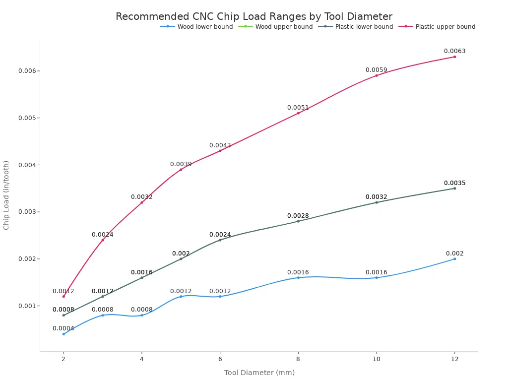
Fast spin rates put heavy bending stress on skinny bits inside a router system. You prevent tool flex by making shallow cuts while moving across the table quickly. Rapid feeds help smaller bits cut soft items without flexing away from line paths.
Good path design keeps your parts accurately sized during every single manufacturing run. Correct chip load control stops sideways pressure from damaging delicate tool flutes. These balanced settings keep your fast carving machine running smoothly for many hours.
Big milling units use strong turning force to push bits through tough, heavy metals. Hard steel alloys push back hard against sharp edges while cutting away stock. You need slower spinning speeds to create the raw pushing force for deep cuts.
Slower spin rates let wide cutters carve big grooves without stopping the drive motor. You handle tough metals by sending steady power through strong mechanical gears. This reliable pushing action guards your main motor during very hard milling tasks.
Taking thick chips puts big physical pressure right on your tough carbide cutting flutes. High turning power forces edges through hard steel, but big chips dull edges faster. You manage wear by tuning your main cutting speed and applying fluid flow.
Heavy milling work needs rock-solid tool holders that absorb hard impacts smoothly. Constant frame stiffness stops bad vibration and helps expensive tools last much longer. Careful tool contact gives you steady, high-quality results on tough metal parts.
A CNC machine's frame layout controls how well it handles strong movement forces while cutting parts. How engineers build the machine body changes how fast it shifts and how much it cuts.
Light gantries glide over long tables while holding flat parts completely still. You can swap direction quickly because the moving bridge parts do not weigh very much.
Makers build fast routers out of light parts like carbon fiber, thin steel, or aluminum tubes. You can speed up at rates from 1 to 2 G across big table surfaces.
Traverse Axis Mass ↓ --> Inertia ↓ --> Acceleration ↑ (1 to 2 G)
When cutting soft MDF boards, you keep fast travel speeds from 400 to 600 IPM at 18,000 RPM. Cutting light passes 0.125 inches deep keeps your machine moving fast without stopping the motors.
Quick direction swaps make light frames shake fast during continuous high-speed cutting passes. You stop high-pitch shaking by using rubber leveling feet alongside thick steel rail plates.
Helical rack-and-pinion parts mesh several gear teeth at once to soak up sharp motion jolts. These drive setups keep your tool moving smoothly along long paths without losing its true position.
Cutting hard metals takes a solid machine setup that soaks up strong tool impacts. Massive, heavy bodies help modern metal factories make good parts every time.
Big industrial mills use heavy gray iron parts like Grade FC250 or Meehanite GA. Tiny graphite specks inside this iron soak up frame shakes in less than 0.05 seconds.
Frame Material Parameter | Cast Iron (Grade FC250 / Meehanite) | Aluminum Extrusion |
|---|---|---|
Elastic Modulus | 108 to 145 GPa | ~69 GPa |
Vibration Decay Time | ~0.05 seconds | ~0.25 seconds |
Material Density | ~7200 kg/m³ | ~2700 kg/m³ |
Solid iron bodies give high stiffness up to 145 GPa to stop frame bending under heavy stress. Your machine frame will not twist under strong power when pushing big cutters through tough steel.
Wide linear guides speed up straight paths, while flat box ways offer broad contact areas to resist massive forces. Heavy machine columns deaden shakes when deep passes force thick cutter flutes through hard steel.
High-torque cutting needs ultra-stiff frames that swallow up continuous, heavy tool pressure. TAIZHENG makes solid units like the 1613 Heavy-Duty Gantry Center and the TMU-400 High Precision 5-Axis CNC Machining Center for top rigidity. These stiff machines boost cutting stability during heavy metal parts production. Picking a heavy iron cnc milling machine ensures top strength for your most important machining center work.
The type of metal or plastic you use tells you if you need fast spin speeds or strong turning force. Picking the correct machine for your job keeps your tools safe and helps you work faster.
Material hardness matters most: tough parts need slower moves, stronger cutting force, and a powerful mill setup, while soft items like wood cut well at high speeds on a CNC router that glides right through.
Soft materials let you work fast by making quick straight cuts. Fast spinning tools trim light parts neatly before too much friction heat builds up.
You need fast spindle spin when working with soft parts so you do not tear the material. Spinning your tool at 18,000 RPM instead of 10,000 RPM gives foam smooth edges. Most fast tools run from 12,000 RPM to 18,000 RPM, but some reach 24,000 RPM. Spinning soft items too slowly makes tools catch and shake violently.
Material | Tooling | Recommended speed/feed | Notes |
|---|---|---|---|
Soft plastics | Solid carbide spiral or O-flute | 18,000 RPM baseline; ~300 IPM | Increase RPM if finish degrades |
Hard plastics | Low-helix chip-breaking tool | 18,000 RPM baseline; ~300 IPM | Ensures clean chip breakage |
Hard plastics | Double-edge V-flute | 18,000 RPM baseline; 125–250 IPM | Delivers excellent surface finish |
Fiber-reinforced composites | Any suitable bit | Run as fast as practical | Use forced-air chip evacuation |
Trimming thin metal sheets takes careful settings to stop the part from shaking. Pick a single-flute spiral O-flute bit so aluminum bits clear out easily while you cut. Hold your thin sheet down tightly with a vacuum pump and a soft board underneath.
Parameter | Recommended value / guidance |
|---|---|
Cutter size | Use a 1/4" endmill on rigid setups; use 1/8" or 3/16" on lighter machines |
Spindle RPM | Aim for 15,000 RPM with a 1/4" cutter |
Cutting speed | Maintain 1,000 to 1,500 surface feet per minute for carbide tools |
Depth of cut | Start at 0.010" per pass on light machines; start near 0.050" on rigid machines |
Plunge feed | Drop plunge feed to 4 in/min when profiling at 20 in/min |
A light cnc router moves fast over large sheets, but thin metals need shallow cuts so the bit does not jam.
Tough materials fight back against sharp edges with strong mechanical resistance. You need strong motor power to cut dense metals without stopping the spindle shaft.
Cutting hard steel takes raw mechanical power rather than fast tool spinning. Tough metal alloys need slow tool rotation to create strong cutting force. A normal cnc router lacks the heavy body needed to handle these rough forces. Slow spin speeds on light machines cause bad tool shaking, quick edge wear, and rough surfaces.
A heavy industrial cnc mill uses gear drive systems to push fluted bits through hard steel. Strong turning force slices through tough metal smoothly without ruining your cutting tools. Heavy iron frames soak up hard hits so your setup stays totally steady while cutting steel.
Space-grade metals like titanium and dense nickel alloys give factory workers a tough challenge. These hard metals create extreme heat and friction while you carve them out. A stiff frame stops tools from bending sideways when taking deep passes in thick metal.
A heavy mill supplies steady turning force even when running at low spin speeds. Modern multi-axis machines make tricky space parts with high accuracy every single time. TAIZHENG builds strong equipment like the HMS-550M Automatic Turning Center to cut tough metals for cars and planes. Using high-torque machines gives you smooth parts and true sizes on high-precision jobs. Matching material hardness to the right equipment makes your whole shop run better.
Deciding on a cnc router vs. cnc mill comes down to what materials you cut. Quick routing speeds help soft stock move through the shop fast. Strong milling torque lets you slice thick chunks off tough metal alloys. Use this simple chart to pick the best path for your project.
Factor | High Speed | High Torque |
|---|---|---|
Material Density | Low | High |
Cutter Diameter | Small | Large |
Depth of Cut | Shallow | Deep |
Check your spindle torque-power curves before you turn on your machine. Looking over these charts keeps your parts accurate and your cuts precise. Look at TAIZHENG CNC machine details to find the best setup for your work. Weighing a cnc router vs. cnc mill makes buying new gear easy.
A cnc router uses quick spinning speeds up to 24,000 RPM for fast, shallow cuts in soft stock. A dedicated mill uses slower spinning speeds with high torque to push wide cutting tools through dense metals.
Fast tool spinning creates strong friction heat against your workpiece. You must move the cutter quickly to make clean material chips. Fast feed speeds carry friction heat away inside flying chips and stop tool rubbing.
Mechanical reduction gearboxes boost motor power at slower spinning speeds. This mechanical power provides strong turning force to push wide cutters through tough alloy steel without stopping your spindle motor.
Cast iron frames like Grade FC250 stop structural shaking in less than 0.05 seconds. Heavy iron bases offer strong frame stiffness to prevent structural twisting during heavy metal removal.
Check your material density and desired depth of cut. You choose fast spindle speeds for soft stock like wood, plastic, or thin sheet metal. You choose high torque setups for cutting dense steel or aerospace alloys.
You can cut thin non-ferrous aluminum sheets on high-speed machines using single-flute spiral tools and shallow passes. However, thick aluminum plates need a rigid cnc machine with strong force delivery.


